With audio codec you have 24 bit depth and sample rate of 48kHz.
With CV outputs, MAX11300 in DAC mode outputs with 12 bit depth and currently Magus outputs it at 50 Hz. The correct way to do it would allow using 750 Hz. I would expect that to remove slewing effect, but make no difference for note tones.
12 bit ADC/DAC channels are sufficient for V/Oct usage if you’re staying within 12 TET. But CV channels on OWL are not calibrated for accurate volt/octave tracking. You might be able to determine its scaling parameters and adjust that. To get general idea, have a look at the calibration procedure that I’ve made for codec. And there’s another one used for Lich, it should work with any device and it might be more relevant as it’s done in patch.
currently Magus outputs it at 50 Hz. The correct way to do it would allow using 750 Hz
Did you say in the other thread this is some sort of bug with the display code?
12 bit ADC/DAC channels are sufficient for V/Oct usage if you’re staying within 12 TET. But CV channels on OWL are not calibrated for accurate volt/octave tracking.
Would this manifest as noise or would it manifest as the voltages simply not being the correct values?
I’ve checked noise levels on the CV outputs on a Magus. With USB power I’m seeing about 1% noise: up to 100mVpp (millivolts peak-to-peak) with a fixed DC output, across 10V.
One percent noise is not so bad in itself, but for 1V/octave pitch control 100mV is quite a lot, considering that a semitone is only 83mV difference. So it could be moving up to 50mV in each direction from whatever the level is, i.e. more than half a semitone.
One thing I noted is that I’m seeing more noise, not less, with both DC power and USB connected. Not sure if that is due to having a crappy adapter (different from the ones we shipped out) or because the internal SPSU has to operate with a higher input voltage. I’ll try with a few different adaptors when I get the chance.
I suspect most of the noise is coming from the LED drivers. I made some experiments a while ago with increasing the PWM frequency, in order to reduce noise in the audio band. I found a solution that worked well for the device I was testing with. Turned out it didn’t work across all devices, and those the changes were rolled back.
I’ve experimented with a few PSUs and there definitely was difference in noise levels. However it dropped with all of them (compared to only USB plugged). I was thinking about comparing to eurorack power, I assume that it should be safe to power desktop Magus from its internal power header?
Also, we might have an option to disable LEDs for situations like this via device settings.
I believe I tested with both power alone and USB+power and could not tell the difference between them by ear. I didn’t measure specifically. Powering the Magus on computer USB only has always been very noisy on all outs so I didn’t bother testing that case.
The LEDs are a very nice feature but if they are going to be a source of noise it might be nice to have the option to disable them. Ideal would be to let a patch disable it (because a patch knows when it needs minimal noise) but if there were even like a global compiler flag for it that would be better than nothing as a short term fix since I am periodically building my own firmwares.
Disabling LEDs somewhat helps, but it doesn’t eliminate noise to the extend where I would use it for pitch CV.
Powering from eurorack doesn’t make any difference compared to PSU that I’ve used - and I hate the fact that I had to remove Magus from its enclosure to install a measly jumper on its inner PCB side
Tried the old commit that changes PWM timings and it eliminates noise pretty much completely (some minor ripple above 20kHz on spectogram). It was rolled backed due to some issue which I don’t remember, but currently it seems to work as expected.So maybe we just rolled back that code too eagerly. There is one problem with those timings - they seem to drive LEDs at double frequency/brightness, meaning that values above 0.5 will crush to white color.
Any LFO looks like crap due to 50 Hz sample rate as output is synced to display refresh. I’ve made a few changes to update DAC every ms (well it would happen every 1.33 ms in reality) and LFOs come out smooth as expected. However, I ended up breaking either display or LED with those changes, so no PR for the time being.
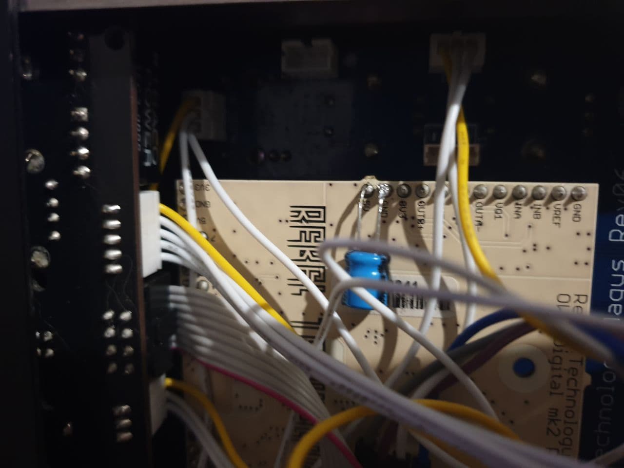
Added a 100u capacitor between ground and 5V as @mars suggested, didn’t see any improvements with noisy firmware code. Photo to check my reading comprehension:
Apparently, the issue that we were running into on that commit was noise from encoder in some cases (i.e. I’ve noticed it in volume change menu). It doesn’t happen to me now, but I’m running different firmware on encoder chip (to make it generate 1 pulse per turn). Also, something goes wrong if I power from USB - display start flashing and lots of whining noise in audio output. I suppose that this is caused by LEDs drawing too much power due to extra brightness.
That all sounds very promising, do you think it would be safe to just reverse 3c7e2301f06dd0ce in my local branch (as long as I don’t power from usb, which I’ve been avoiding anyway due to noise)? 2x power LEDs is not so big a problem, I was willing to disable them altogether…!
Okay it took some time but I’ve tested reversing 3c7e2301f06dd0ce and now the chords sound quite good! The LEDs ARE pretty bright.
On my 3-voice VCO, the notes sound noticeably noisier when I’m feeding in all three Magus-parameter CVs instead of just one. But I suspect that’s probably an element of how the VCO works, not the Magus.
In testing, I do find something weird still. Now that the noise problem is fixed, if I test using Midi2CVTriplet from this repo GitHub - mcclure/MagusPatches: Patches for the rebeltech.org magus (Sorry— I haven’t uploaded it to rebeltech .org/patchlibrary yet because patchlibrary doesn’t support directories, and I use one) and plug my VCO into the Mordax data tuner, I see:
Play C1: VCO plays C1 plus about 50 cents
Play C2: VCO plays C2 plus about 15 cents
Play C3: VCO plays almost exactly C3, maybe minus 10 cents
Play C4: VCO plays C4 minus 40 cents
Play C5: VCO plays C5 minus 50-60 cents
In other words, the parameter span is not exactly scaled to the 5V 1V/oct scale. Close-by notes are roughly correct, but if you play a C1 and a C5 at the same time they will be about one semitone “off”.
Testing with the CV output ( so making the patch the basically the same as https://www.rebeltech.org/patch-library/patch/Midi2CV ) I find there’s some divergence but less so, the gap from C1 to C5 seems maybe 60 or 70 cents “off”. Assuming nothing is wrong with the VCO, I assume this is what the “V/Oct calibration” feature in the Magus now is for?
But as antisvin points out, the V/Oct calibration will not apply to the parameter patch points? So I will need to use something like antisvin’s calibration patch if I want those to line up?
So we’ve had some progress with this, but it’s not too encouraging yet.
Old code had buggy control over LEDs brightness (only a few values accidentally worked correctly due to repeating bits pattern - 010101 or 101010), this was fixed and I’ve added UI page. Now you can set global brightness!
That was the end of the good news, because after applying that old patch over the new code with low brightness I don’t see considerable improvements. I wonder if the fix could be related specifically with excessive brightness?
It looks like applying that old patch also added coil whine in headphone outputs. But it was mostly gone if I lower brightness. Do you get anything like that on older version?
The calibration menu is for V/Oct inputs and outputs on audio codec. It was done before FW supported calibration officially and works in a different way compared to what was added later (it starts from inputs rather than output). It doesn’t require DMM, but CV source to supply 1 & 3 Volts. There’s no way to calibrate ADC/DAC channels at the moment, but you could do it in your patch. You could even store those results on flash and load in patches that require this info instead of hardcoding it in code.
You need to get offset & multiplier values for each values. If firmware code is confusing, have a look at V/Oct conversion code that uses it - OwlProgram/VoltsPerOctave.h at develop · pingdynasty/OwlProgram · GitHub . Note that Magus UI reads integer data from codec, but you probably can use normalized float when calibrating CV channels.
All VCOs have some level of tracking error and 5 octaves is a fairly big range. So you should be using precision DMM, otherwise this is meaningless - you can’t tell DAC error from VCO tracking error. Can’t Mordax measure voltage directly? Otherwise, you can experiment with octave range (using multiplier parameter for calibration) to correct tracking deviation. In this case it doesn’t mater if DAC or VCO is wrong, you’ll just try to correct tracking as much as possible. This would be at the cost of getting wrong values for other VCOs with the same calibration data.
You need to get offset & multiplier values for each values
How widely applicable will the calibration offset/multiplier be? Will it be specific for a device, or if I get the calibration for one Magus will it apply to other Magus devices? Can it vary for a single Magus unit over time?
Since nobody calibrated MAX11300 channels on this device before, it’s not known how much they would vary over time. I would expect them to be fairly consistent. There’s no chance that calibration would be useful for different device as this is done to correct per-channel deviations in particular chip.
Other things to consider:
It may be possible to use calibrated codec input on device itself to measure voltage. This is convenient, but would have higher error compared to a precise DMM.
You need to add resistive load to the outputs if you use multimeter to calibrate them. I think that using a stackable cable to connect to another V/Oct input is the easiest way to do it.
I think per-channel CV calibration is something we’ll want to add. With resource storage, this should now be a bit easier to do in a way tailored to each device.
CV channel calibration is definitely something worth adding, but it should probably be done as a factory calibration and stored aside from user data (i.e. written in the end of bootloader). Obviously DIY builders would have to do it themselves, but asking everyone to recalibrate 20 channels on Magus due to erased storage is not great.
For CV channels we would want to apply calibration in FW to make sure that all data is available for every patch/integration. Naturally we can’t do that to codec. But what has to be done for codec is adding support for multiple channels of V/Oct calibration. This would require changing API in C++/FAUST V/Oct scaling code to allow users choosing channel number.
So, a year later, I have come back to this… I thought I found a solution that didn’t require a complex calibration step. However, the noisy patch points are still preventing me from using the Magus usefully.
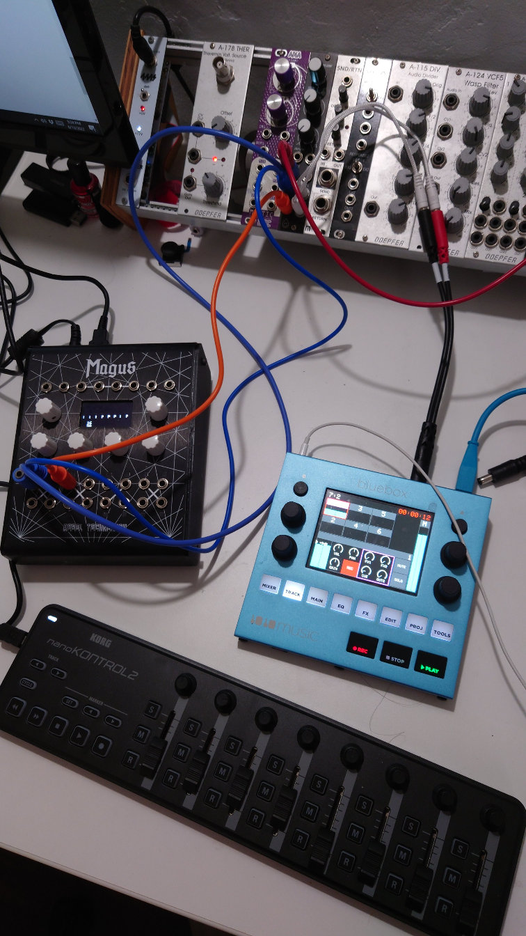
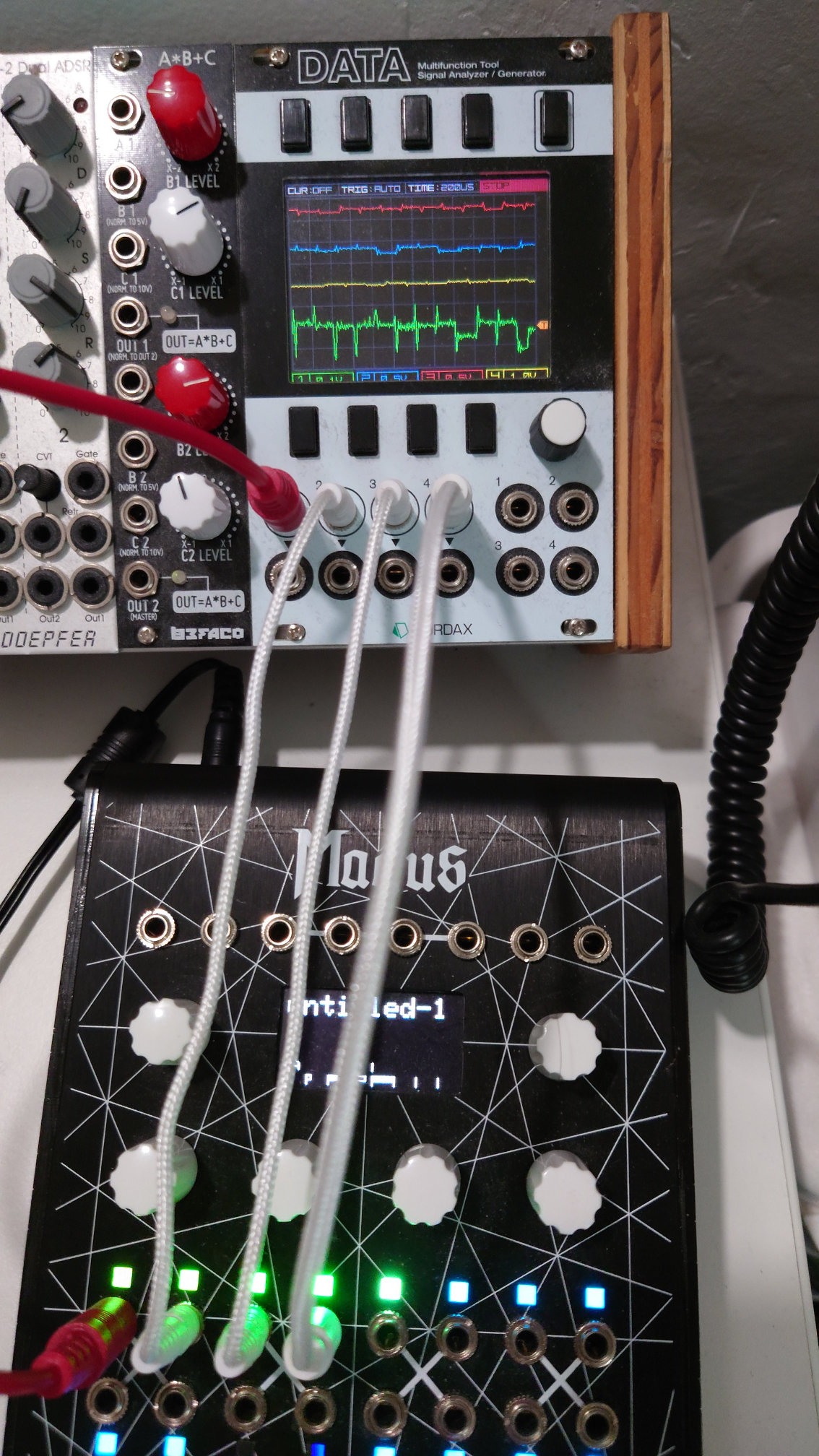
I hooked up a nanoKontrol2, which is all continuous sliders and knobs. Don’t need to calibrate your notes if they aren’t quantized to begin with! I figured I could tune my notes “by ear” like a 0-ctrl (but a 0-ctrl with 8 CV patch points, which would be pretty great). Here is the patch I am using (git 307174f) and here is my setup:
So I am running on DC-adapter wall power only, and I am using the nanoKontrol to ear-tune 3 CV values, which correspond to the 3 voices of the VCO. To my disappointment the “kazoo” effect was as bad as it ever was. Here is a recording of a 3-voice chord: starting as a super saw; turning up “detune” which adds some natural spread to the VCO; then turning “detune” up a little higher; then switching to squarewaves and turning the detune down to 0. (The detune actually almost rescues it by drowning the Magus detuning in intentional detuning, but) you can hear the pure output at the start and end and it sounds pretty unmusical.
Note, that is with the LEDs at their normal default brightness. However, I get the noise even with the LEDs turned down to brightness 0:
I am pretty sure that in my tests last year, disabling LEDs did noticeably help. But this sounds actually a little worse than the first test even (probably because the chord is higher pitched so pitch variance is more noticeable). This seems to suggest that the noise problem is not the LEDs themselves, but rather something else that incidentally happens when LED is on? Maybe when LEDs are at 0 it is still sending LED brightness data, it’s just attenuating it to zero or near zero. I would try disabling (rather than just attenuating to 0) the LED brightness but as described elsewhere I cannot build v22.4.
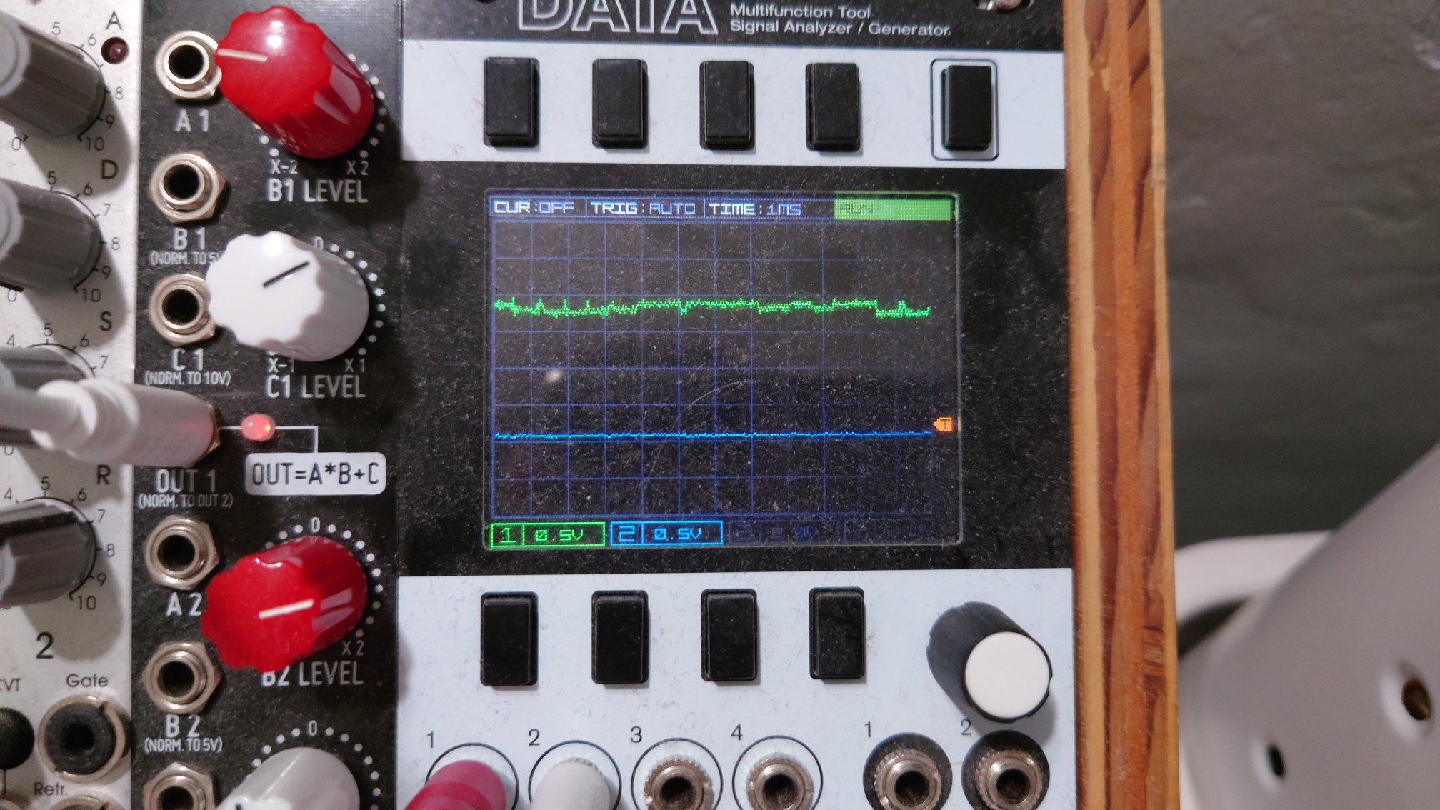
I had trouble during this test getting the Mordax tuner to work but here’s a constant signal from the Magus side by side with a cleaner constant signal from the A*B+C:
As you can see the signal is just not noisy but it’s a very complex noise pattern full of small digital glitches, actually it would be kind of neat noise if I were triggering it on purpose
Is there any way to get usable CV output on the Magus parameter ports? I was hoping to make a sequencer app based on the NanoKontrol2, but if I cannot even get a single clean note out from the parameters, that is pretty discouraging.
If one division on the Mordax is 500mV, then that looks like at least 200mV peak-to-peak of noise. That’s at least twice as much as I have recorded in my testing.
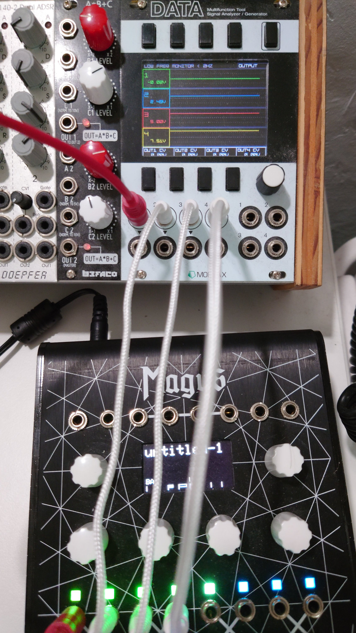
To exclude other possible causes or contributions, could you pls test it with this silly patch: OWL Patch Library – Rebel Technology
It sets different DC levels on parameters A to E.
Okay so I’ve just tested with another device. Found two interesting things!
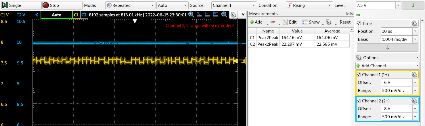
Firstly the noise level on the A, B, C and D outputs are higher than expected, at between 150 to 180mV. This is with v22.4 on a desktop Magus with USB power, but the only DC adapter I have produces similar results. It is quite a bit more than what I’ve seen before, so I wonder if there might be some regression. Adjusting LED levels does not affect the noise very much.
The second unexpected thing is that the output at maximum, on parameter E in that patch, has very little noise. It can be seen as the blue line, C2, in the screen grab. I’m not sure what that means, apart from that more testing is needed.
I tested the patch…
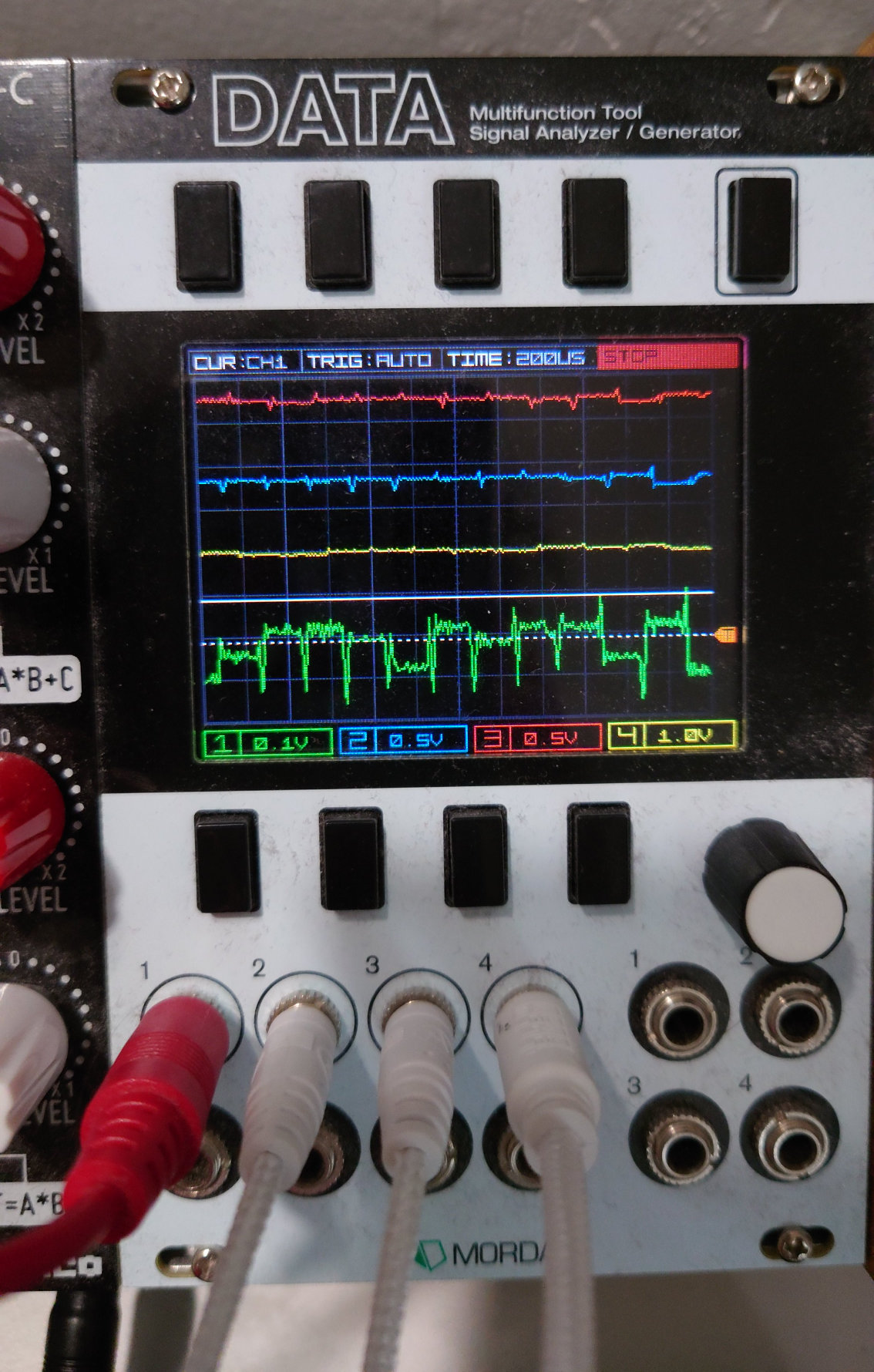
The Mordax unfortunately does not seem to be set up for precision measurements and due to a limitation of the Mordax I could not investigate all the parameters at the same scale level. But, what I found on my unit was:
The “spikes” in the noise appear to happen consistently about 200 μs apart.
Parameter 1, measuring at scale 0.1: High 0.1 V low -0.25 volts
Parameter 2, measuring at scale 0.5: 2.64 high 2.33 low
Parameter 2, measuring at scale 0.5, different display offset: 1.98 V high - 1.72 or 1.77 low
Parameter 3, measuring at scale 0.5: 2.94 or 2.89 V high - above 2.64 low
Parameters 4 and 5 voltages were too high to get into display range at a useful scale.
So although these measurements are not precise it looks like I got a consistent noise range of 0.3 to 0.35 V regardless of the signal voltage.