
I’ve recently done a bit of soldering on Magus board to connect debugger. This allows you to debug firmware, which is essential for anyone trying to extend it rather than just writing patches. You should not do any hardware modifications if you’re not comfortable soldering and I can’t be responsible for any damage that may occur.
I’m using common Chinese ST-Link v2 clone that connects with jumper wires. Here’s some info how necessary soldering can be done:
-
Open your Magus, gently pull digital board. You can unscrew jack nuts and remove IO panel to have enough space for this.
-
Locate necessary pins (you’ll need at least SWDIO, GND, SWCLK, 3.3V). You can use older revision of Owl digital board to find them (pin layout is compatible with newer version in this regards). Double (or triple) check that you’ve found correct pins.
-
Desolder old pins. You can just put them on the back side and be done with it (i.e. if it’s eurorack module and there’s enough space in your case), but you won’t be able to close lid on Magus because wires from the pins would be too tall.
-
Replace straight pins with angled pins, pointing them inside digital board and solder them. Here’s what it looks like:
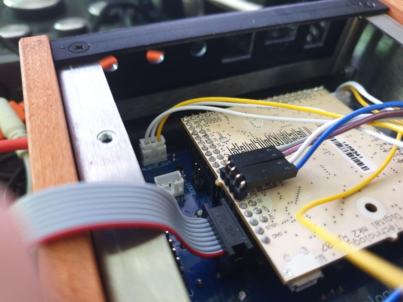
Pin length doesn’t really matter as long as they’re soldered. But pointing longer side towards the blue board would make aligning pins easier.
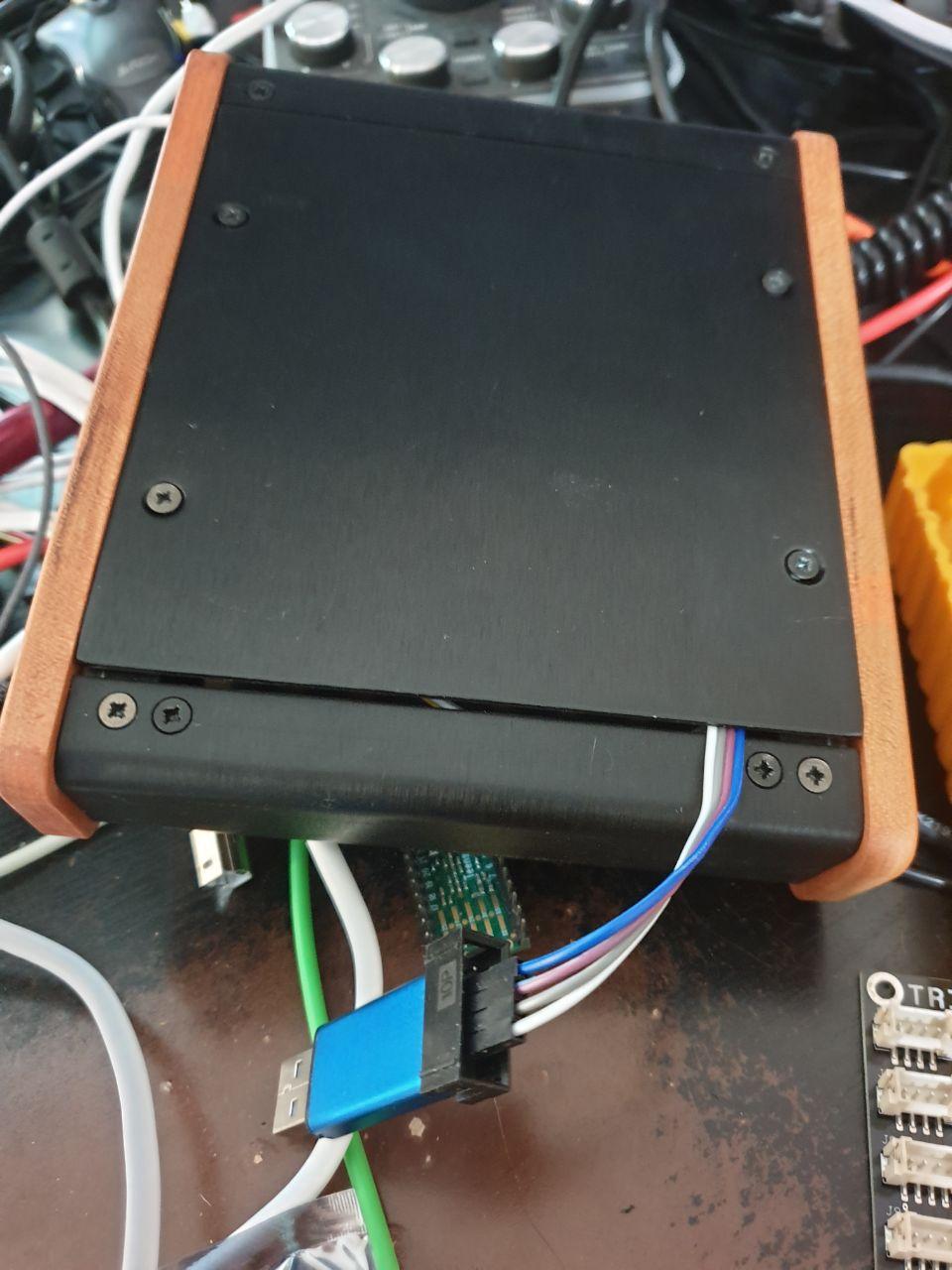
End result is that you can connect programmer and close lid on Magus, leaving only a few mm gap:
I could explain how to get started with setting up firmware building if there would be some confirmed interest in this topic.