CV/Gate Output on 5 and 6 from Faust or C++?

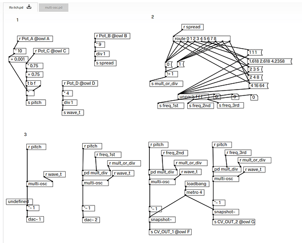
Hi everyone! I’m learning how to create patches for the Witch in Faust and C++. I thought a good start would be to create a patch that is similar to the Quad LFO patch.

The Quad LFO patch outputs on F, G, and (I think) the two channels of the audio out.

My questions are:

  • What are the names of these outputs? (They’re labeled “Trigger Outputs” in the docs and “5” and “6” on the physical device.)
  • How do I target these in my code?

Here’s a screenshot of the main Pd file (the Quad LFO patch link isn’t accessible, due to some server issues)

Hi,

On Witch you can set LED state as buttons 1-4 and output CV gate state as buttons 5-6. Parameters F-G set CV outputs.

You can read how to use them in FAUST and C++ docs for OWL.

Perfect - thank you so much!

The docs were very helpful, but I think I’m missing something.

My patch behaves as expected if I use faust2jack - I can see that the rate of output from F, G, B5 and B6 are controlled by my sliders.

But, on the device, only outputs F and G are producing signals.

import("stdfaust.lib");

// Slider for LFO1 rate (in Hz)
lfo1_rate = hslider("LFO1 Rate[OWL:A]", 1, 0.01, 10, 0.01);
lfo1_out = hbargraph("LFO1>[OWL:F]", 0, 1);

// Slider for LFO2 rate (in Hz)
lfo2_rate = hslider("LFO2 Rate[OWL:B]", 1, 0.01, 10, 0.01);
lfo2_out = hbargraph("LFO2>[OWL:G]", 0, 1);

// Slider for LFO3 rate (in Hz)
lfo3_rate = hslider("LFO3 Rate[OWL:C]", 1, 0.01, 10, 0.01);
lfo3_out = hbargraph("LFO3>[OWL:B5]", 0, 1);

// Slider for LFO4 rate (in Hz)
lfo4_rate = hslider("LFO4 Rate[OWL:D]", 1, 0.01, 10, 0.01);
lfo4_out = hbargraph("LFO4>[OWL:B6]", 0, 1);

// LFO function
sinusLFO(rate) = os.osc(rate) : si.smoo;

// Oscillators
lfo1 = sinusLFO(lfo1_rate) : si.smoo : *(0.5) : si.smoo :> lfo1_out;
lfo2 = sinusLFO(lfo2_rate) : si.smoo : *(0.5) : si.smoo :> lfo2_out;
lfo3 = sinusLFO(lfo3_rate) : si.smoo : *(0.5) : si.smoo :> lfo3_out;
lfo4 = sinusLFO(lfo4_rate) : si.smoo : *(0.5) : si.smoo :> lfo4_out;

// Process function with parallel LFOs
process = lfo1, lfo2, lfo3, lfo4;

Is there something other than hbargraph that I should use for B5 and B6?
There are a few suspicious places that may cause it to work incorrectly, i.e.:

  • invalid parameter range for outputs (-0.5…0.5 instead of 0…1)
  • not using attach primitive

In addition to that, you don’t need to smooth your signal 3 times and you don’t need to smooth sine LFO at all. The only place that might benefit from smoothing here is parameter inputs (LFO rate) if you intend to output results as audio, and you don’t do it.

Also, you’re outputting 4 channels into 2 channels of audio that are available on Witch, this will sum them in pairs. To match original PD patch you would have to generate audio (and use attach to force computing it, but cut 2 audio channels with ! operation).

You should probably start with the sample patch from FAUST docs that sets gate output and experiment with it to adapt to your needs.

That’s excellent advice, thanks for looking over my code.

Back to the docs I go!

I ended up finishing my patch that outputs gates on the 4 CV outputs (at 1x, 0.5x, 2x, and 4x based on the position of Knob E).

For the benefit of anyone interested in outputting a gate on B5 or B6 on the Witch, you can do something like this:

lfo4_out = hbargraph("LFO4>[OWL:B6]", 0, 1);
lfo4 = ba.impulsify(sinusLFO(main_lfo_rate * 4)) : lfo4_out;