Hooking up the Owl Digital & Custom Board

Hello,
I am looking at setting up the owl digital in a breadboard test, and had a few questions about the schematics for the pedal.

  1. I am wondering on the Pedal schematic what VCC/2 is referring to? is this 5v or 3.3v divided by 2? Any time I see the 5v or 3v3 it never refers to either as VCC.

  2. I do not understand the schematic between BYPASS pin and PE4 using the transistors. One of the transistors ends is not connected to anything, and I am unsure of what it is doing in general. I understand it is used for the off state of the FX_OUT_L on the 4PDT footswitch.

3)In the schematic when it refers to SHELL connecting to ground, is that the actual casing of the pedal?

  1. I was also planning on setting up my own Owl Digital board using the chips that are present in the one you can purchase, however I am wondering if there are any resources or if anyone know how to load the owl bootloader onto a custom board.

Thanks in advance! Any answers would be helpful!
Kevin

  1. VCC/2 is the reference point of the codec, which is nominally 1.65V. It shouldn’t be used to power anything, only to bias the audio input or output circuit.

  2. That’s probably the Millennium Bypass circuit which is used to indicate the bypassed state to the MCU, without interfering with the audio signals.

  3. SHELL here is the casing of the pots, which also physically connect to the enclosure.

  4. By far the best thing to do if you’re doing any serious work with the board is to get an STLINKv2 programmer and connect it to the SWD pins. You can then load any code you want, inspect memory, and do full in circuit debugging.

If you don’t fancy that then the MCU has a built in DFU bootloader which is activated by setting the BOOT0 and BOOT1 pins. Information on activating DFU mode and loading the bootloader is here:
https://hoxtonowl.com/mediawiki/index.php/Hardware_DFU

hth,

Martin

BTW the easiest way to connect the OWL Digital to e.g. OwlControl is by wiring USB_GND and USB_VBUS to GND and +5V. It will then be powered over USB.

So I got the firmware loaded (for now I only have Freeverb as the only patch loaded) and I am trying to get this dev board set up with a guitar input and output to an amp to test the freeverb patch. I have linked an image of the way i have it set up currently. I am using the owl pedal schematic to set up the input and output filters.

Now the problem is that when playing the guitar through this setup it came out VERY distorted and noisy. You can tell that there is some sort of output from the owl digital board, and it changed slightly when messing with the potentiometers, but it in no way resembled a normal guitar output. I took a video of the sound, and i can post as a comment tomorrow to see if there is a simple reason why it is messing up.

So, basically, do you have any suggestions for setting this up the correct way? Am i missing anything that could cause the output signal to be so messed up? Or could it simply be the patch i was trying to run? Right now i am going for the basic ability to take a mono input perform the modification of the signal, and give the output.

Also one of the things a friend was asking about was what voltage do the opamps need to be at?

Thank you!
Kevin

Getting good audio performance is difficult, you have to examine closely every part of the signal path, analogue and digital, and all the different power supplies.
I would suggest you put a patch on which does nothing but copy the data from input to output so that you can measure DC and AC performance going through the codec. Use a scope to look at the signals before and after the analogue input and output stages.
You can also use OwlControl to put the codec in bypass mode, and play around with the input and output gain to see if that affects things (which could indicate clipping somewhere). But without a scope you’re fumbling in the dark…

Hello,

So i was in the lab today and we made some progress. We were able to get rid of the extensive noise on the output. We realized that we set up one of the GND pins incorrectly. The rest of the night went as follows.

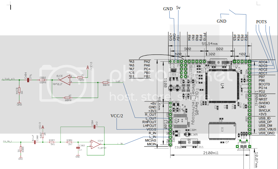
We initially started with a problem where the input was clipping due to the biasing on the opamp. After inspection of the codec datasheet we realized that it need the 3.6v maximum analog input voltage. Because some of the notes we were playing were getting distorted from this, we decided to put a simple voltage divider to attenuate the input signal slightly to make sure it did not clip, we will change this to an internal potentiometer later on to allow the user to get that slight distortion of desired. Is this a common problem when setting this up? or did we set it up incorrectly?

After this we were able to get a clear output, however it was VERY small, and we had to turn the amp up very high to hear the output. We added a 100x gain amplifying circuit to account for this. There is still some noise in the output (we want to get rid of it completely if possibe), but it is less than before. Is there a reason the output from the owl digital board is so small? is this expected?

Lastly, since we are now able to get an output to go through to the amp and hear it, we were testing a simple gain and simple delay effect on the board. I am not sure if we maybe had the bypass mode set up on accident, but we were unable to get the effect to actually modify the signal. These effects worked fine in the online compiler and testing webpage, but did not work on hardware. Where on the owl control can i set the bypass like you said? I cannot seem to find it (and does it tell me if it is enabled or not). Also what should the bypass pin (PE4) be set to when we do not want it to bypass? the circuit for it was slightly confusing, and i want to make sure we have it going to the right value to keep bypass off.

I will go back to the lab during this week to try to work out some of these kinks, but I figured i would post my problems and questions along with any fixes i had.

Thank you, (sorry for the long post)
Kevin

Hi Kevin,

what’s the project you’re working on? Links / photos appreciated!

The best reference is the firmware and schematics. If you look at how PE4 is handled in the OwlWare source you will see what the expected transitions are; it’s probably a GPIO with internal pull-up that the circuit will pull low to activate, but could be the other way around.

The OWL Digital board gives direct access to the codec audio pins, so yes the WM7831 datasheet is the best reference for this. There are PGAs on both the inputs and HP outputs which also determine output level and gain.

There is also the ‘soft bypass’ mode which you can activate using OwlControl. This sets a register on the codec which makes it pass the input straight through to the output. This is different from the true bypass circuit implemented by external circuitry in the pedal.

We are working on a digital and analog multi effects pedal. I will post some pictures and videos once we get the pedal up and running! Right now we were able to get the hardware to run a gain patch, so i am working on making a few more patches for our project. Also going to set up a custom pcb, hopefully in place of the owl digital board, using the owl firmware, but if not, a board that we can plug the owl digital into.