Hello!
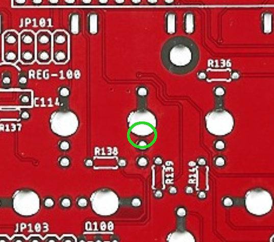
If manual control works then there’s only really one resistor (or the pot itself) which could have a problem, and that’s R130 and it should be 100k.
If you put e.g. a 10V DC signal into CV C jack, then with your multimeter you should see 10V at pin 3 of the CV C pot.
At the pot wiper, pin 2, you should see a lower but still positive value with the pot fully clockwise. Moving to the resistor, the right side (near the op amp) should show the same value as the pot wiper. The left, edge side is connected to the op amp virtual ground and will be show 0V regardless of the signal. With power off, you can continuity test the left resistor pad of R130 and op amp IC101 pin 2 to verify it’s connected. Do the same with the right resistor pad and the pot wiper.
tl;dr: check the solder points at R130 and the CV C pot and verify the resistor value, then you should find the problem!

