Porting Openware to Daisy

I know Martin ordered one too, which means I can’t be banned for discussing a competing product - Daisy — Electro-Smith :slight_smile:

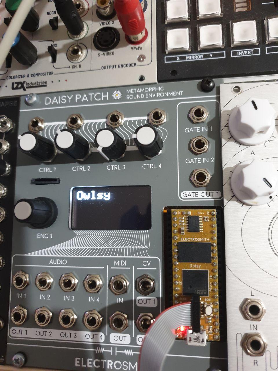
My kickstarter shipment has finally arrived and I’ve started digging into details of their hardware. My main interest is porting OpenWare to it, but I’m not sure how realistic would that goal be. Daisy board is using an MCU from STM32H7 family and it would take lots of effort to port current firmware. This was expected, but I haven’t initially checked specific H750IB MCU datasheet, which creates more difficulties.

While it should perform about 4 times faster (at least according to ST marketing presentations), it belongs to value line of H7 family. So it only has 128k flash on MCU itself. Daisy also has 8MB QSPI flash chip, but we won’t be able to write it from firmware like we do for normal flash. We could probably move patch writing code to a version of midi bootloader that it would use, then switch to bootloader for writing patches. Something like this would probably work in linker script:

FLASH (rx)        : ORIGIN = 0x8000000, LENGTH = 64K    /* Bootloader on flash*/
SETTINGS (rx)     : ORIGIN = 0x8010000, LENGTH = 64K    /* Writable flash part - should be used for storing settings from firmware */
APPLICATION (rx)  : ORIGIN = 0x90000000, LENGTH = 512K  /* QSPI flash - firmware part */
STORAGE (rx)      : ORIGIN = 0x90080000, LENGTH = 7680K  /* QSPI flash - patch storage part. That's one hell of a lot of patches */

So we’ll have a bootloader and writable flash section (i.e. for storing settings), plus memory mapped QSPI chip for firmware and patches. Midiboot would be writing firmware (or patches) in indirect write mode to chip, then switching to memory mapped mode and jumping to firmware.

I will spend some time trying to port midiboot here, we’ll see if this would lead to something.

The good thing is there’s a proper library for hardware access that looks quite usable. Also there’s cubeMX project that I’ll use as a starting point.

Looks like directly integrating code from Daisy would make things too messy. It has its own controllers for hardware state based on HAL, in some cases doing the same things that is done in OpenWare in a different way. So I will probably just copy code that we need (it’s MIT licensed).

Currently I’m trying to refactor FlashStorage to use a separate base class from which QspiStorage could inherit. I think it would be possible to share their code that relies on reading, while write would be very different. QspiStorage would have to switch between read-only and write-only mode. Write mode would switch QSPI to indirect mode and use registers for hardware access. For reading we could switch back to memory mapped mode and reuse existing code (this may require something like template parametrization to replace hardcoded flash addresses).

StorageBlock class could be reused as is (again, template parameters may be required) if we move its write operations to FlashStorage/QspiStorage. There are only 2 such methods - write() and setDeleted(). I think this is acceptable, since those methods are not called by StorageBlock itself, but only by FlashStorage class.

As of today, there are 2 commercial eurorack modules based on Daisy (aside from official “Daisy Patch” from Electrosmith):

  1. QuBit surface - physical modeling voice with 8 note polyphony - which finally dethroned MI Rings

  2. Noise Engineering just announced Desmodus Versio, a fairly advanced stereo reverb. They’ve mentioned that there would be open source firmware release by the end of the year, however it’s not clear if that would include DSP code or just a template project for writing firmware from scratch.

And their own hardware schematics were released under MIT license

Well, the bootloader port can already compile and run on device. Some things don’t work yet, so it’s debugging time (and it may take a while).

Adding QSPI storage class that I’ve mentioned before is not necessarry, because QSPI writes can only be performed by bootloader and it would use low level functions (similar to eepromcontrol stuff, but for qspi). But I had to make changes to FlashStorage in order to setup 2 separate storages - for settings and patches. Other projects would use a single storage as before, this is abstracted by a few macro definitions and backwards compatible.

Recent progress:

  1. Ported QSPI code from Daisy’s codebase to bootloader - confirmed that it can successfully initialize memory-mapped mode.

  2. Got USB stack working, it identifies as full speed audio device.

Next: add firmware uploading. QSPI code for writing was also ported, but not tested yet. I obviously don’t have a firmware that would work, so I will simply confirm that FW for other device can be copied, then will check that the “magic word” is available under correct address. This would be sufficient to start work on FW port, but later more stuff would have to be added - we’ll have to load patches from bootloader, because we won’t have write access to QSPI flash when firmware is running from it.

Some more progress:

  • ported SDRAM driver from Daisy
  • flashing firmware works!
  • stack pointer is present on QSPI after flashing!
  • new firmware starts booting… of course that was FW from another device that was just used for testing

Now the problem is that we can’t fit current FW on 128kb flash, so I have to use bootloader for booting and initializing QSPI. But then I won’t be able to use debugger. So if I will run into any serious issues that require it, I think I’ll have to create stripped down FW version (i.e. no LUTs or ARM libraries), use it to troubleshoot hardware and then create fully functional FW that would load from flash.

It’s alive! Made a smaller firmware that omits LUTs for fast math. It can run from main flash (takes ~96k) and is usable for debugging. Other than booting without errors, it’s not particularly exciting, as there’s plenty of peripherals to be added. Will start with display, because we already have driver for it made for Magus.

And display works! This is reusing existing SSD1306 driver. Unlike Magus, it uses hardware CS pin. I’ve also enabled DMA, not sure why we’re not using it on other hardware. Couldn’t make sense why it wouldn’t work, until I’ve finally noticed that RCC timings that daisy used had some difference from their sample Cube project. Will experiment with them a bit.

Added ADC inputs support (bound to params A-D). Also some preliminary code for encoder. Current code for timer driven encoders won’t work as they are not connected to timer channel that supports encoder mode. For now I’ve made a software based encoder class that runs once for every UI update. I might convert it to use interrupts or drive it with timer. And it has debounced button, but this stuff will need some more work.

Ported most of UI code from Magus screen, replacing encoders with ADC params. V/Oct calibration is not possible because audio codec has AC-bound input, requires pulling up an unconnected pin to disable it.

Will be adding gates and DAC next.

Current code: GitHub - antisvin/OpenWare at daisy

How about:

  • Working codec
  • Scope menu

Finished various UI updates. All functions now work, which was a bit of a challenge - originally it was using 2 encoders, here we have one. So I’m using second “virtual” encoder that get updated when switch to alternative mode (i.e. on click in one of control menus that has alternative functions - like encoder sensitivity in play menu). I’ve also removed calibration and volume pages, since they are not usable with this hardware.

And all CV related stuff is configured and tested. That would be ADC, DAC and 3 GPIO channels.

There are 2 major tasks left:

  1. Second codec support
  2. Patch saving. This would be time consuming task, because we won’t be able to write patches from main firmware - QSPI is read-only at this time. I think I’ll load incoming patch to RAM, then set magical value and patch info at some specific address, switch to bootloader mode and check for that address. Then we can finally store that patch on flash.

Serial MIDI is not tested yet, I will probably leave this to later time unless it would happen to just work.

Managed to get serial MIDI working. Old callback that we had for other devices wouldn’t work as UART register differs on H7. First attempt to use similar register fields wasn’t working for me either, but apparently the same functionality is covered by HAL functions. So this code got UART in order:

  if(__HAL_UART_GET_FLAG(&huart1, UART_FLAG_IDLE)){
  __HAL_UART_CLEAR_IDLEFLAG(&huart1);
  HAL_UART_RxCpltCallback(&huart1);

I think this should be compatible with F4 and likely most if not all other STM MCUs.

Pinging @mars , I think I need some feedback on the following.

Looks like currently OwlProgram is able to process only stereo patches. I’m trying to make a new multi-channel alternative to SampleBuffer class that would be able to handle:

  1. more than 2 channel of audio (I guess something that Noctua would also need)
  2. data exchange with more than 1 codecs that won’t require copying their data into a single buffer in firmware.

The latter would mean that we will skip parts of audio stream to handle double buffering correctly. I will generalize this to using up to 4 codecs, since it would only require reserving an extra bit in in audio format descriptor. Something like this would be used:

#define AUDIO_FORMAT_24B16_2X       0x10
#define AUDIO_FORMAT_24B24_2X       0x18
#define AUDIO_FORMAT_24B32          0x20
#define AUDIO_FORMAT_24B32_2X       0x22
#define AUDIO_FORMAT_24B32_4X       0x24
#define AUDIO_FORMAT_24B32_8X       0x28

#define AUDIO_CODEC_DUAL            0x40
#define AUDIO_CODEC_TRIPLE          0x80
#define AUDIO_CODEC_QUAD            0xC0

/*
 * This would work correctly only with 24B32* formats!
 * Others have inconsistent channels mask.
 */
#define AUDIO_CHANNELS_MASK         0x0F
#define AUDIO_CODEC_MASK            0xC0
#define AUDIO_FORMAT_MASK           0x3F
#define AUDIO_CODECS(FORMAT)        ((FORMAT & AUDIO_CODEC_MASK) >> 6)
#define AUDIO_FORMAT(FORMAT)        (FORMAT & AUDIO_FORMAT_MASK)
#define AUDIO_CODEC_CHANNELS(FORMAT) (FORMAT & AUDIO_CHANNELS_MASK)
#define AUDIO_TOTAL_CHANNELS(FORMAT) (AUDIO_CODEC_CHANNELS(FORMAT) * AUDIO_CODECS(FORMAT))

Then the loop in PatchProgram would have to do something like this:

    for(;;){
      pv->programReady();
      for (int i = 0; i < AUDIO_CODECS(pv->audio_format); i++)) {
        samples->setStartChannel(i * AUDIO_CODEC_CHANNELS(pv->audio_format));
        samples->split32(pv->audio_input, pv->audio_blocksize);
      }
      processor.setParameterValues(pv->parameters);
      processor.patch->processAudio(*samples);
      for (int i = 0; i < AUDIO_CODECS(pv->audio_format); i++)) {
        samples->setStartChannel(i * AUDIO_CODEC_CHANNELS(pv->audio_format));    
        samples->comb32(pv->audio_output);
      }
    }

This shouldn’t affect older devices - they would still be processed as stereo by old SampleBuffer class. We could theoretically also use new code for 32bit stereo processing, but I don’t think there’s any reason to do it.

Exposing codecs number overcomplicates things, so I went with plan B and just store codec outputs in a single merged buffer. This works and I can get results as 4 channel stream. This is based on just visualizing buffers with the scope UI. Of course I will still need a multi-channel aware StreamBuffer replacement to process this data in patches.

For some reason, I get a SAI DMA error on startup with 2 codecs, so I will look into this - maybe I’ll have to replace HAL tick based delay with NOP loop like most codecs do. There’s no visible problems from this (could be a few buffers lost on startup). Once I solve this, it would be time to finally start work on patch loading.

Somehow I can’t get firmware to run after bootloader jump. Linker script is edited, VTOR is set to symbol exported from LD (spotted this in Magus sources). The FW runs only if used with a different linker script and stored on flash. I think there could be some peripheral init issue that I’ve missed in FW, otherwise it could be something wrong in LD script.

However, now I’m thinking that read-only QSPI is too much of a limitation:

  1. Can’t write patches from application code, need to go back to bootloader

  2. Requires separate settings storage on flash

  3. Filling that settings storage would require overwriting bootloader in order to erase their shared sector on defrag

So I will try to convert it to loading FW as BootROM, luckily there are cube sample projects for both use cases.

This would require allocating more RAM as we’ll have to load full FW image there. But this is probably acceptable. Flash would only be used by bootloader in such case, potentially we could have a bigger bootloader with additional features - loading FW ROM from SD card, backup FW ROM slot, display support, etc.

Another interesting side effect from BootROM support is that we could overwrite FW image on QSPI flash even from running application.

Flash storage code (converted to template usable with QSPI too) doesn’t handle junk data very well. Ran into case when it got hard fault due to reading data that was previously used for storing firmware image. Looks like it can dereference header variable that can point to invalid address in certain cases. There was a check that header address is less than storage end, but beginning wasn’t checked.

Besides this invalid address issue, alignment for block headers was checked only when they were written. This was source for another hard fault - due to derefencing addresses without proper alignment.

With those issues fixed, junk data can be properly discarded if it ever reaches patch storage.

Dynamic patch loading works (in glorious quad channels!). Next stop - QSPI storage for patches (code is written, but probably needs some love to start working).

Patch storing / loading works with QSPI storage. The stack overflow I’ve ran into was solved by increasing flash task stack size from 512 to 1024 words, which was most likely due to QSPI writies made in 256 byte pages.

Currently I’m using a trivial patch that copies inputs to outputs just to confirm that it runs. I can’t run serious DSP code, because FW is built without fast math tables due to limited space. Addin LUTs would require using bootrom that I’ve tried to get working earlier. I think that it was not working due to FW issues that got fixed later, so I’ll return to this in the very end.

Next milestones:

  • check if defragmentation code works

  • enable caching, which would require using separate memory section for DMA buffers with caching disabled

Some numbers about cache efficiency. I’ve measured CPU load for a trivial patch that basically copies inputs to outputs. It was very obvious that H7 core is severely throttled by IO from running code and data in D1 domain RAM.

  • No cache - 14% load
  • Instruction cache ON - 13% load
  • Data cache ON ~3.5% load
  • Instruction + data cache ON < 1% load

Which shows that data cache gives most improvements. Instruction cache is not particularly effective without data cache, but helps a lot when data cache is enabled.

Now, DMA exchanged bypasses caching completely, so for all DMA buffers we have to do one of the following:

  1. Use a separate memory section that is not using cache (configured by MPU settings) - this will be done for most large buffers (audio data, probably also MIDI and digital bus)

  2. Use cache, but discard old value before reading - this is done for ADC values

  3. Use cache, but write it to memory before reading (using clean and invalidate call) - this is done for graphics params array. Haven’t fully understood how it interacts with cache yet, but this approach is the only way that I could get it to work correctly.

For option #2 we must align data to cache lines (32 bytes) in order to not invalidate data belonging to something else. For #3 this alignment is not mandatory, but it’s better to use it to avoid evicting data that is stored nearby graph parameters.

I’ve added 2 macros for changing object alignment and for moving to non-cacheable section.

I’ve compared that patch’s performance on Magus - 3% CPU used. Besides being 3 times faster, Daisy was processing twice as many channels. But performance on larger patches would likely drop along with caching efficiency.

I’ve finally ran out of things that need fixing in firmware port, it’s time to start dealing with last major task - setting up bootrom loading. It’s sort of written, but wasn’t functional last time. Turns out that I was booting broken FW, so maybe not that much is left to get everything running.