Hello everyone!!!
I am a newbie and would like to update the firmware of AC/DC.
Can anyone help me figure out how to do it?
Thank you! <3

Hello everyone!!!
I am a newbie and would like to update the firmware of AC/DC.
Can anyone help me figure out how to do it?
Thank you! <3
Hi,
You can read about it here
And this is the latest firmare release from which you need the ACDC.bin file.
Hi antisvin!
Thank you for your answer!
I’ve tried following the guide, but after flashing the ACDC.bin the unit does not show the startup animation anymore and is not recognised by the tool either.
Failed To Connect To OWL
Is the unit bricked or is it a boot loader issue?
Thank you!
You know what, I’ve just tested the official build myself and noticed that it breaks USB. However, it’s not bricked - the default patch is running. But without USB you can’t flash another firmware!
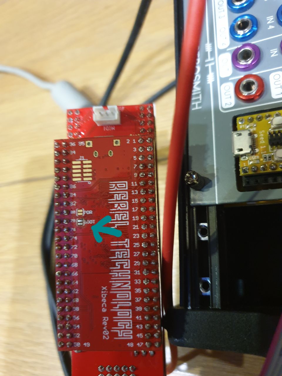
However, it’s possible to force DFU mode without USB. In order to do that, you’ll have to short a pad when the module is booting. Use a small screwdriver and make sure not to touch anything else. Then you will be able to load a working version of firmware.
Just to avoid confusion, here’s a photo to help you locate it:
I’ve already let RebelTech/Befaco know about this issue, so a correct update is expected soon. I’ve build the latest firmware manually with correct libraries, so you can use it if you don’t want to wait:
ACDC.bin (101.9 KB)
Hi Antisvin!
Thank you for your amazing support!
I’ve tried shorting the pads, but nothing happens. I still receive the error “Failed To Connect To OWL.”
I’m not actually sure if something is running, as turning the volume pots does not light up the respective channel LED (or maybe I misunderstood what you meant by “default” patch).
The steps I’m following are:
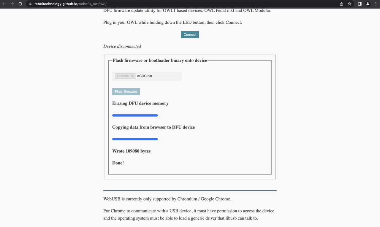
I have a screenshot of my first ACDC.bin flash attempt (before you compiled the correct build). I think I forgot to press “Enable Advanced Mode” on the DFU tool before flashing the firmware. The button is at the very end of the page and, being hidden, I directly pressed “Flash.”
Hope i can still save the unit!
Thank you again 
Yeah, the “default” patch is what you have preinstalled - it’s like a 4 channel VCA. You can connect some CV source to one of the channels and set it gain to max to see that firmware and that patch runs.
Based on your post, you’ve flashed it to the wrong address and no firmware would be able to run in this situation. Still, the one that is released doesn’t seem to work for me (but the same code worked when I’ve compiled it myself).
DFU mode should always be usable as it’s handled by flash address that we can’t overwrite. I think that your steps have incorrect order - you must shorten it while it’s not powered, then turn on the power. And make sure that USB cable is disconnected - I think it might end up powering from the cable and you won’t get a proper reboot. You might have to make a few retries as the pad is small and it might be hard to get a good contact.
Feel free to make a video if my explanation won’t help.
I’ve tried many times with different tips, such as screwdrivers and other metallic objects.
As you can see/hear in the video, I’m following these steps:
short the unit
power on while shorting pads
connect USB
receive the error message “Failed To Connect To OWL”
Also, feeding the input with a hot signal does not show any LED activity.
The unit seems to be powered off, and it’s cold to the touch even after being plugged in for a while.
Here is the video showing the steps I followed: owl.MOV - Google Drive
The unit also had the peculiarity of not lighting up the LED on channel 3 (and just on that channel) when the pot was maxed out (the LED correctly lit up during the boot animation and the recording was fine as well).
Something tells me that it’s not the luckiest one ahah
Hi Antisvin,
Still nothing from my side.
The module seems to be dead. Do you think it’s possible to buy the Xibeca board as a spare part?
Thank you!
Ok, so about your video. First of all, you’re changing parameters, but they won’t do anything in DFU mode or without a running firmware. With correctly flashed firmwre firmware you’ll still need to send something to input to get indicator working. Even then you need to have a patch that sets LED values, but in your case it should be still present, just no firmware to run it.
You could try writing to Befaco support and see what they can offer you. I think they’re waiting for chips availability to make a new batch of Xibeca boards, but might have some spares. Or you might send them your board to flash the firmware.
Note that even without DFU you can flash it after soldering another connector (you’ve probably noticed those 2x5 pads for it). You’ll also need ST-Link v3 mini programmer if you’ll want to do it yourself (costs within $10-15 typically).
Hi Antisvin,
I tried contacting Befaco, unfortunately the only answer I received is “buy a happy ending kit”.
Xibeca boards are not available separately.
I would like to try the ST-Link way, do you have any resources on how to flash the firmware from it?
Thanks in advance!
Well if it’s a DIY build and you’ve also noticed some problem with LEDs, maybe their “happy ending” would make sense.
Either way, for flashing firmware without DFU you would need:
I’ve confirmed that Xibeca can get flashed this way. The debug header is SMT, but not too hard to solder as long as you have a decent iron with a small tip and understand what you’re doing. It’s soldered to “J1” header on board.
I’ll explain remaining steps if you end up with all of the above, but it’s a matter of running openocd with correct config file and parameters.
hank you, Antisvin.
I know that the Happy Ending Kit is a good solution (and the prices for the EU are actually fair). However, I don’t really care about this module. Instead, I care about learning new things. That’s why I would like to go down this path regardless of the possible outcome.
Thank you for sharing your knowledge. I’ll reach out again once I get the ST-link.
Hi Antisvin,
I hope you are doing well.
I have finally got the ST-Link V3MINIE. In the meantime, I was able to solder the connector onto the Xibeca board and install OpenOCD.
I am looking forward to make the next steps!
Hey @tetraechos
Ok, hopefully we’ll finally manage to get this working. Here’s a rough outline of how I’ve flashed it (writing from memory, could be missing something):
The programmer’s header has 10 pins, but the cable has 14. So it should be centered and you’ll have 2 unconnected pins on each side. Connect it so that the red cable strip is on the side where Xibeca board has a dot near the header. On the programmer’s side it would be near the “CN5” label if your programmer is the same as mine. It won’t burn if you connect it upside down, just turn it around on one end if you suspect that it might not be connected correctly.
IIRC, I didn’t power it from eurorack, but rather from its microUSB port. It might work either way, but this is safer
Looks like there’s no config file for Xibeca in OWL repo, I’ve used the following based on something that was done in another project:
source [find interface/stlink.cfg]

transport select hla_swd
set WORKAREASIZE 0x1c000

source [find target/stm32h7x.cfg]
set _TARGETNAME $_CHIPNAME.cpu0

reset_config srst_only
openocd -f /path/to/xibeca.cfg -c "program /path/to/ACDC.bin verify reset exit"
This was done on Linux, but in theory it’s supposed to work on Mac/Windows too. If you’ll run into some issues, you could try this alternative to openocd - STM32CubeProg - STM32CubeProgrammer software for all STM32 - STMicroelectronics . You’ll have to figure out how it works yourself, but I think someone on this forum already used it for flashing other OWL boards.
If you say that you’re mostly exploring things, you could use ST-Link to explore firmware and learn how microcontrollers work. Not sure if you had this sort of hacking in mind by “learning new things”.
Hi Antisvin,
Hope you are doing good, I’ve finally got the time to try this.
I’m receiving this error:
openocd -f /Users/Mac/Desktop/xibeca.cfg -c “program /Users/Mac/Desktop/ACDC.bin verify reset exit”
Open On-Chip Debugger 0.12.0
Licensed under GNU GPL v2
For bug reports, read
http://openocd.org/doc/doxygen/bugs.html
Info : The selected transport took over low-level target control. The results might differ compared to plain JTAG/SWD
srst_only separate srst_nogate srst_open_drain connect_deassert_srst
Info : clock speed 1800 kHz
Info : STLINK V3J8M3 (API v3) VID:PID 0483:3754
Info : Target voltage: 3.301401
Info : [stm32h7x.cpu0] Cortex-M7 r1p1 processor detected
Info : [stm32h7x.cpu0] target has 8 breakpoints, 4 watchpoints
Error: read_memory: read at 0x5c001004 with width=32 and count=1 failed
Error executing event examine-end on target stm32h7x.cpu0:
/opt/homebrew/Cellar/open-ocd/0.12.0/bin/…/share/openocd/scripts/target/stm32h7x.cfg:237: Error: read_memory: failed to read memory
in procedure ‘program’
in procedure ‘stm32h7x_dbgmcu_mmw’ called at file “/opt/homebrew/Cellar/open-ocd/0.12.0/bin/…/share/openocd/scripts/target/stm32h7x.cfg”, line 170
in procedure ‘stm32h7x_mmw’ called at file “/opt/homebrew/Cellar/open-ocd/0.12.0/bin/…/share/openocd/scripts/target/stm32h7x.cfg”, line 260
in procedure ‘stm32h7x_mrw’ called at file “/opt/homebrew/Cellar/open-ocd/0.12.0/bin/…/share/openocd/scripts/target/stm32h7x.cfg”, line 242
at file “/opt/homebrew/Cellar/open-ocd/0.12.0/bin/…/share/openocd/scripts/target/stm32h7x.cfg”, line 237
Info : starting gdb server for stm32h7x.cpu0 on 3333
Info : Listening on port 3333 for gdb connections
Error: read_memory: read at 0x5c001004 with width=32 and count=1 failed
Error executing event examine-end on target stm32h7x.cpu0:
/opt/homebrew/Cellar/open-ocd/0.12.0/bin/…/share/openocd/scripts/target/stm32h7x.cfg:237: Error: read_memory: failed to read memory
in procedure ‘program’
in procedure ‘ocd_process_reset’
in procedure ‘ocd_process_reset_inner’ called at file “embedded:startup.tcl”, line 1193
in procedure ‘stm32h7x_dbgmcu_mmw’ called at file “/opt/homebrew/Cellar/open-ocd/0.12.0/bin/…/share/openocd/scripts/target/stm32h7x.cfg”, line 170
in procedure ‘stm32h7x_mmw’ called at file “/opt/homebrew/Cellar/open-ocd/0.12.0/bin/…/share/openocd/scripts/target/stm32h7x.cfg”, line 260
in procedure ‘stm32h7x_mrw’ called at file “/opt/homebrew/Cellar/open-ocd/0.12.0/bin/…/share/openocd/scripts/target/stm32h7x.cfg”, line 242
at file “/opt/homebrew/Cellar/open-ocd/0.12.0/bin/…/share/openocd/scripts/target/stm32h7x.cfg”, line 237
Error: timed out while waiting for target halted
** Unable to reset target **
shutdown command invoked
Well I’m away from my hardware until the end of the month, so right now can’t confirm if latest openocd works. Just in case, you might try flashing it with default ST-link config by running it like openocd -f interface/stlink.cfg -f target/stm32h7x.cfg -c "program /path/to/ACDC.bin verify reset exit"
I was using a slightly older version of openocd and likely older ST-link hardware, not sure if any incompatibility should be expected from that.
I did find a report of the same error, but happening after flashing the program - https://www.openstm32.org/forumthread7683 . It looked like a bug in openocd, but editing one of its internal config files is not that great as a solution.
If you want to try something else, maybe ST flashing utility would work instead of openocd - STM32CubeProg - STM32CubeProgrammer software for all STM32 - STMicroelectronics .
Alternatively there are open source st-link utilities that can be used instead. I’ve used them in the past for simple reading/writing flash when no debugging was necessary.
Hi @antisvin,
Thanks for getting back to me. I hope you’re doing well.
In the meanwhile i’ve updated the ST-link firmware and tried the command line you suggested, but unfortunately, it still doesn’t seem to be working.
"
openocd -f interface/stlink.cfg -f target/stm32h7x.cfg -c “program /Users/Mac/Desktop/ACDC.bin verify reset exit”
Open On-Chip Debugger 0.12.0
Licensed under GNU GPL v2
For bug reports, read
http://openocd.org/doc/doxygen/bugs.html
Info : auto-selecting first available session transport “hla_swd”. To override use 'transport select '.
Info : The selected transport took over low-level target control. The results might differ compared to plain JTAG/SWD
Info : clock speed 1800 kHz
Info : STLINK V3J10M3 (API v3) VID:PID 0483:3754
Info : Target voltage: 0.914209
Error: target voltage may be too low for reliable debugging
Error: init mode failed (unable to connect to the target)
in procedure ‘program’
** OpenOCD init failed **
shutdown command invoked
"
Using STM32CubeProgrammer I have the following error: “No STM32 target found if your product embeds Debug Authentication, please perform a discovery using Debug Authentication”
I’m not sure if it’s useful:
Powering the Xibeca Board over USB = 0.00 V detected from ST-Link
Powering the Xibeca Board over Eurorack PSU = 0.86 V detected from ST-Link
Both Openocd and Cube are not able to reach the target, what am I doing wrong?
Thank you for helping me!
Yeah, all is well, I’m on vacation actually (sort of).
Hmm, well previously it showed proper 3.3 voltage, I’m not sure why this happens. Is it the same if you use previous config or is that due to new firmware on ST-Link? I suspect that now openocd/cube programmer don’t see it because there’s some problem with power. If it’s software related, this should be reversible. But it could be some problem in DIY build or just an upside down ST-link cable on one end.
Also, make sure to disconnect USB cable from ACDC device port when you use the programmer - in some hardware setups 2 USB connections gave me weird problems in such situation in the past, probably some kind of ground loop.
Hi Antisvin,
Hope you are enjoying your vacation time!
Voltages dropped after my first attempt of flashing with Openocd (shown in my message from yesterday), every other attempt had V reading between 0.3 and 0.91
The config file is the same as before.
I’ve tried to reverse the cable but then the V readings started to be even more incoherent, so I assume the cable was connected properly (red stripe facing the white O).