Gate in / gate out

Hi,

quick question re the digital i/o. chances are i’m simply missing something, but as I couldn’t find any obvious directions as to how to use them (they’re missing, for instance, in the pd template?), poking around in the code confused me even more.

specifically, as per schematic (rev-02): In_D = PB7, Out_D = PB6; now in device.h, it looks as if they’re defined the other way round?

#define SWITCH_A_PIN GPIO_Pin_6 (#L86)

#define PUSH_GATE_OUT_PIN GPIO_Pin_7 (#L132)

i assume the error is in the schematic?

thanks!

on a related note, i fail to recompile owlware.

things hang with

No rule to make target Libraries/CMSIS/DSP_Lib/Source/TransformFunctions/arm_bitreversal2.o’, needed byBuild/OwlWare.elf’. Stop.

make -d tells me it can’t find arm_bitreversal2.o first (“does not exist”), then fails to remake it.

the weird thing is it does build arm_cfft_f32.o, arm_cfft_radix8_f32.o, arm_rfft_fast_f32.o and arm_rfft_fast_init_f32.o; but it refuses to build arm_bitreversal2.o

any hints?

thanks
ah, wait. ok, so it looks as if there’s arm_bitreversal2.S, but “make clean” removes it?

compiles if/when i manually add arm_bitreversal2.S or use arm_bitreversal.c via libs.mk ; any way to change this (odd) behaviour?

finally, i’m getting a linker error

… OwlWare/./Source/ProgramManager.cpp:307: undefined reference to `buttonChanged’
collect2: error: ld returned 1 exit status

it compiles when i comment out L#307.

hello!
Yes I think there is an error on the OWL Modular schematics, if you trace it out to the OWL Digital board it shows that the pins have been swapped.

make clean shouldn’t remove the .S file, and it is required for compilation. Are you building on Windows? I think the problem is a non-case-sensitive match in the clean target, I’ve removed that.

buttonChanged() : it seems the signature in the definition didn’t match the declaration for some reason, not sure how this ever got compiled! Fixed and pushed.

Please pull the latest from github and it should all work!

Martin

ah phew, obvious enough … anyway, works now. thanks!

about the gate input though: physical pins aside, i’m still trying to get my head around how this works, semantically i suppose. ie how one would differentiate between the tact switch and the gate input?

for instance, there’s an enum in stompbox.h, but none of the entries obviously corresponds to the gate input:

enum PatchButtonId {
BYPASS_BUTTON = 0,
PUSHBUTTON,
GREEN_BUTTON,
RED_BUTTON
};

ditto for the two callbacks (pushGateCallback() and pushButtonCallback()), they largely seem to do the same, ie setButton(PUSHBUTTON) or clearButton(PUSHBUTTON)

in other words, they’re treated as one and I’d use the gate input by calling it PUSHBUTTON?

e.g. / as in? adsr.gate(isButtonPressed(PUSHBUTTON), getSamplesSinceButtonPressed(PUSHBUTTON));

"I’d use the gate input by calling it PUSHBUTTON?"

Yes, that’s the idea. The reason being that by design, the same patches should run on both Pedal and Modular OWLs. That’s also why the gate in/out is labelled PUSH on the Modular.

"adsr.gate(isButtonPressed(PUSHBUTTON), getSamplesSinceButtonPressed(PUSHBUTTON));"

Exactly that.

There are ideas to make the button/gate more flexible, so that you can set it to toggle or momentary action for example. That way you could use GREEN_BUTTON / RED_BUTTON as toggle states. I’m still not sure what the best use is. But for the time being, use PUSHBUTTON to mean that either the button is pressed down, or the gate is high.

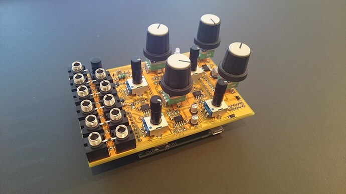
ok, got it. thanks again; just re-flashed the firmware with in- and outputs adjusted and everything is working properly now (i’m using the digital board with custom ctrl board, that’s way)

Cool - post some photos!

it’s very similar, just a bit smaller:

That’s really cool, nice work Max and thanks for sharing!

Hi, to follow up on the push jacks in PD. I thought I read that one is an input, and the other an an output. Is that correct? And I see in another thread a mention of it not being propagated to PD yet. So, for the functional time being in PD, the left push jack is input, and the right jack is not implemented?

Can we, just for the record, codify exactly what the PD input channels are? I see several hints, but just to be crystal clear…

Channel-A
Channel-B
Channel-C
Channel-D
Channel-E (“exp”)
Channel-Push

And someday it might be two inputs, Or two outputs, or an input and an output, so could those be Channel-Push-In and Channel-Push-Out? Or maybe Channel-Push-Left and Channel-Push-Right? PD is super-not-happy with me sending bangs to Channel-Push with Channel-Push also receiving, at the moment.

Those names are correct.

I believe Channel-Push output should be working now too!

PD is super-not-happy with me sending bangs to Channel-Push with Channel-Push also receiving

Oh of course! That’s never occurred to me. Ok we’ll have to come up with some solution.

Personally I’ve never liked the ‘Channel-…’ names, because they’re not channels, they’re parameters!
It would be nice to support configurable, descriptive parameter names. Hopefully this will be possible with a forthcoming release of Heavy.

Hi Martin

Can I get confirmation what the Gate I/O is for Max/Gen~? are the ‘@ID Push’ for Input, what about gate output?

Also is the Expression input still called “E” (problematic in Gen)?

thanks

Yes E is taken by Euler’s constant in Max, so the fifth parameter is called Exp - and the gate/pushbutton input is Push.
I don’t think you can send parameters or gate /button signals from Gen though, or am I mistaken?

Hi Martin

thanks for clarifying that

you can generate a signal out of gen~ that would be good enough to trigger something - something a bad as this patch would do it


----------begin_max5_patcher----------
538.3ocwU80abBCC+Y3SQTdb5FBB+4N1Kq8ywzzTNH5HUPBJIzQUU+tuDGX8
5V4Fsic6ErrIw1+r+YmGCCvGkiLMF8IzWPAAOFFD.lbFBlzCvczwpVpFNFVv
9t73c3c9eYXiFv7GlsnMOzx.SyVDCcxASKy.NHYxZO0T0vEm9lhUY7IPx9hn
3cnzzTmfTFka+RhhQec5N7Zvw13+wjhY268s4gdl2KX7OOuMxbwbfINaOEF5
9rakfsR10wDleCsmnFFxFXTkQ0tVjGuLxIY4.jyKchj7XPKdAnmN6+dESaSO
pgKEm4s7zC96CtY9yqWURdGUkEn.8TEsCcif1wP2htwFDaXsR5nsKFGscDDB
wKR77jkXHwuUFR7FxPLMbM5jjoAZhQhLMLji17YDTmluPKWvpjCB3VjMfIk.
89LuXhI4Fnd0RDA+OlST0x6crf3nxMbAQA.tBxkZ+ku0t+Fh5mod+Mfsj.K.
KS.XlcIvd3ZP0WZrugpkJzsa37seMX9gKA47+i8W2HcxFr1eBuSCqo6uDdy9
iipvsfEJ+xC5Pjc1eIR0xAU0bQa9MUzyAuloMbA73xYGp7EmogWWyDmCyZtl
drkUuLKasoS4JxlrqV1bXEYCT.StJoS9ZSm2S0wyjn882yT5IeBYhc53Noxo
teGnxEd0TPUwtmOed3sLLUY47FKgeP4mQFK7DYbmrloDC7IVrMxOE9C.6yLY
8.
-----------end_max5_patcher-----------

but i’m wondering how does one address that dac gate output? it seems a shame to have it there but not be able to utilize it

I dont really have a clue whats going on as I’m a basic/newb max for liver and potential OWL user and recent discoverer, I’m curious as well to try and wrap my head around whats possible in terms of gate input and output,

In Gen~ with OWL are we able to take a gate input for instance and then trigger something with it, or divide/multiply/count the triggers (for instance to create swing clock and shuffle clocks from a trigger, or delay every 3rd or fourth note/trigger by a particular amount?

also is it a possibility to create an LFO or CV voltage from inside Gen/max as this would be awesome for making utilities and CV sources?

cheers in advance for any help clarifying these details, I’ve looked everywhere on forums and documentation and I cant be sure from what I’ve seen that this is possible.

@Speakerbug in an OWL Gen patch you have access to parameters A, B, C, D, Exp, and Push.
Exp is the extra CV input on the OWL Modular, or the expression pedal input on the OWL Pedal.
Push is an on/off parameter which is activated by pushing the LED button, or, on the Modular, by the PUSH trigger input.
There is also the stereo audio inputs and outputs, which are DC coupled.
So yes you can use Push for trigger and gate inputs. You could also use thresholding on any of the parameters or audio inputs.

What you can’t do at the moment is to activate the Push trigger output from inside Gen. We are hoping to have a solution to that at some point.
Meanwhile you can use the audio outputs. Because they are DC coupled you can put out any CV signal: LFOs, triggers, envelopes, gates. If you adjust for offset and scaling you can also use the audio inputs and outputs for 1V/octave pitch CV with very accurate tracking and high precision, e.g. to make arpeggiators or quantisers.

1 Like