The epic digital bus thread

I’ve just received notification that Kickstarter items for Trill have been shipped. Anyone else getting them?

@mars Martin, can you post some info about the EXT output on Magus? I think it was mentioned before that it could be usable for I2C, but no details were given about connected pins and such.

The Magus PCB has three 3-pin JST PH connectors marked BUS1, BUS2 and BUS3.
BUS1 is a serial port, BUS2 is I2C, and BUS3 is used for the mini-jack MIDI out.

Bus connector pins, function, name on OWL Digital board and MCU assignments are:

BUS1 Pin 1: UART TX, OWL A3, PA2
BUS1 Pin 2: GND
BUS1 Pin 3: UART RX, OWL A4, PA3

BUS2 Pin 1: I2C SDA, OWL A17, PB9
BUS2 Pin 2: GND
BUS2 Pin 3: I2C SCL, OWL A16, PB8

BUS3 Pin 1: +5v via 220R resistor
BUS3 Pin 2: GND
BUS3 Pin 3: UART TX via 220R resistor, OWL A3, PA2

On the Magus Modular, BUS2 is connected to the EXT jack on the expander, with pin 1 on tip, pin 3 on ring, gnd on sleeve. BUS3 is connected to the MIDI jack in the same way.
On the Magus Desktop, the EXT jack on the back of the device is connected to BUS3, to provide MIDI output with the mini-jack to DIN converter. To access I2C instead, unplug the cable from BUS3 and plug it into BUS2.
For reference, this is Trill I2C info

So the pins are no longer a mystery - and this probably belongs to github docs repo too. I already have some experience with software side of I2C on STM32 MCUs - enough to get started.

I’m still not sure about connecting VCC line. The best idea I’ve had so far is not to use ext jack, but add another one with TRRS connector to opposite site of Magus. It would be connected to bus2 + VCC pin of digital board. And maybe it’s better to solder it to a prototype board to secure everything inside Magus (pull-up resistors should also be aded)

Martin,

Is BUS1 intended to be used with the digital bus code? That code itself looks pretty good to me, so how far is it from being ready for official release?

I’m considering another approach for connecting sensors - use something like Arduino to deal with sensor polling and just send latest data from it to Magus. This way the issue of powering them with an extra wire is also solved. And I think it would take way less effort to make a peer for digital bus running on Arduino compared to adding I2C support to firmware.

So the sensors have arrived and I’ve confirmed that there’s no problems compiling their sample code on Arduino.

After some consideration, I’ve decided to have a separate board acting as peer for Magus. The plan is to use ChibiOs on another STM32F4 Nucleo board and communicate with Magus over digital bus.

As a first step, I’ve enabled it in Magus repo fork. DMA was not configured for UART in Cube project and there were a few regressions in digital bus code (looks like .available method is missing and should probably be replaced with .getReadCapacity). It compiles now, but I’m not sure yet if everything works.

So far I’ve created a new project on ChibiOs, made sure it boots and can print over serial port (this is for debug printing over bufferized non-DMA driver). Next step is to try reading from UART with DMA - I suspect that there could be something that I’ve missed and it would take a while to troubleshoot.

I’ll probably add a menu entry for digital bus status and some other info (list of discovered peers?)

ah yes, the bus protocol!

As you have probably found, it is intended to pass 4-byte USB MIDI messages with the addition of peer discovery, plus efficient exchange of 16-bit parameters, buttons, and binary data.

It has been used in an OWL Rack configuration with 5 devices, there were some timing and reliability issues but I think they were resolved.

Yeah, I’ve figured out what it is by now. Decided that it should take less effort to get bus running on Magus vs writing I2C implementation from scratch. Even if it won’t end up usable for some reason, I think I should have at least working support on Magus and will try to connect it Owl.

It looks like current implementation does nothing other than debug printing for commands/messages/data handlers. I probably could get away with just passing data as MIDI, but adding respective callbacks to patch class for receiving entities and service calls for sending them doesn’t seem too hard.

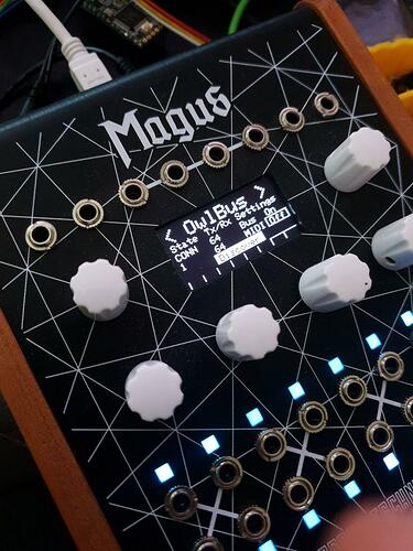
How about UI shot:

Ran into a few issues that don’t block my development, but would likely have to be fix before digital bus can be enabled in production firmware:

  1. It looks like if bus is enabled and nothing is physically connected to UART, Magus hangs on boot. If there’s a connected device (not necessary responding to UART or even powered), it boots fine. This is problem for non-IWDG-enabed bootloader as device gets bricked this way.

  2. If connected devices gets disconnected, bus connection changes its state to idle as expected. But a few seconds later Magus decides to commit harakiri - display and LEDs turn off, but I still see its MIDI device.

I suspect those two issues could be a symptom of attempt to run discovery process when nothing is connected.

1 Like

So far I’m only getting garbage as input on Nucleo board on the other end of serial connection. Port settings between devices don’t seem to have any discrepancies. This could be a cable issue, so I’ll be making a new one by soldering jump wires to audio jack to eliminate intermediary audio cable.

But first I’ll rebuild Owl firmware for Owl Rack platform and will solder a few extra pins to the back of Owl1 digital board (found empty pads for PA0/1 and ground). This way I can at least connect Magus and OWL to check if I can get peer discovery to succeed.

Cool! Do you have the code in a repo? I could try to reproduce.

Wasn’t committing yet, but I will cleanup this stuff and let you know when it’s pushed.

For now I’ve updated my Owl and she feels fine without a connected device (I’ve confirmed that bus enabled in app settings and it checks bus status). I think the issue could be happening because Magus uses transmit DMA on his UART, unlike Owl1 that only supported interrupts on that pin.

Ok, I’ve pushed current code here - GitHub - antisvin/OpenWare at magus-digital-bus

It’s based on your develop branch rebased on feature/iwdg. Added the following:

  1. Enabled UART port with TX/RX DMA in Magus

  2. Bus support is enabled if you build with PLATFORM=MagusBus

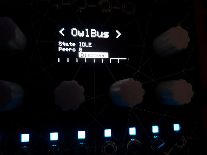
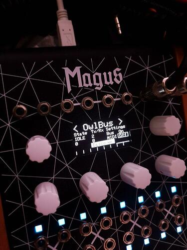
  3. This flag also adds “OwlBus” menu that is more useful than screenshot posted before

  4. Made a few fixes to get digital bus working (i.e. renamed ring buffer method names were referenced)

  5. Owl bus code only replaced DMA with IT transmit call on pedal, so it didn’t work correctly on euro module.

  6. I had some errors when building Owl FW in debug mode, I think I’ve fixed it by using the same settings as were present in owl2.mk and a variable in LD script .

It’s possible to use menu to enable/disable bus and midi forwarding in settings (use left encoder in bus menu).

One more thing. I’ve checked and disabling bus in settings doesn’t resolve this rebooting issue. Disabling bus code with build flag does solve it.

Also, I’ve noticed that Magus was hanging during boot process with about 10% probability. I don’t think it was happening without bus enabled. It could be the same issue, but if it boots it runs consistently for a few seconds.

I will try running it with interrupts instead of DMA to see if that makes any difference. And maybe there’s some issue with watchdog code due to added DMA for UART, so I could rebase it on develop branch without experimental IWDG branch code for testing.

I think I’ve figured it out. First of all, it was not watchdog’s fault - rebuilding without it gave me crashing without reboot. So IWDG actually did what it’s supposed to and rebooted to bootloader. I’ve spent some time debugging and looks like the issue was due to printf in error() function in Source/errorhanders.c called by interrupt due to no bus connection. I don’t have a programmer with semihosting support, so it was crashing Magus if debug was enabled.

Updated UI, in case if anyone is reading this:

1 Like

Looks like I’ve figured out the reason why it was hanging on cable disconnect. Apparently that’s what USART global interrupt handler code does as generated by Cube. I’ve noticed that Prism source had some extra code written and copying it fixed the issue AFAICT.

Also moved my commits to another branch that doesn’t use watchdog (it’s not needed while I’m loading FW with programmer)

I’m still not able to reach “connected” state, but I see that disconnecting cable changes it from “discovery” to “idle” for a moment, then Magus continues discovery. I should receive some spare jacks for making a shorter cable in a few days. Until they arrive, I’ll be using using Owl for testing - will try to read digital bus data from UART on another Nucleo board or on Bela Mini using jumper wires.

Turns out I can read UART data on Teensy from both Owl and Magus. In case of Magus, this is using the same suspicious cable. So I’ll try to connect them with Teensy as proxy for different UARTs to see if that can get them to communicate this way. Otherwise it could be some software issue (digital bus code wasn’t even compiling initially, so it could have some regressions now).

Finally, I’ve got Magus and Owl to connect using Teensy as UART hub. However, it takes a while for this to happen. Discovery succeeds only after 64 frames have been sent. I’ve confirmed that it happens repeatedly. Teensy itself has a Serial.flush() method that should send all bufferized data and I call it after each frame. I think this happens on STM32 side and this is what I’ve assumed to be a faulty cable, so I’ll be checking what’s going on there.

I suppose that OwlRack configuration was using ring bus topology. I’ve noticed that Teensy 4.1 exposes as much as 8 separate UARTS, so it could be an interesting way to make multi-device hub (plus it has an extra USB port and good USB midi support - could be midi forwarding peer itself).

Also, I’m considering drilling Owl’s panel eventually to install a proper jack there for connecting to UART.

Found the reason why receive buffer was not working correctly

“bus_rx_buf.getCapacity()/2” evaluates to 512 / 2 / 4 = 64 frames, so DMA callback doesn’t get called until this much data is available when we start with an empty buffer. I think this variable should be replaced with value 4 in order to get triggered when a single 4-byte frame is available. Confirmed that it works and discovery happens after single frame arrives.

However, reconnect after rebooting a single peer doesn’t seem to work. This could be a bug in protocol state machine.